描述

一、PCA9685簡介
The PCA9685 is an I2C-bus controlled 16-channel LED controller optimized for LCD Red/Green/Blue/Amber (RGBA) color backlighting applications. Each LED output has its own 12-bit resolution (4096 steps) fixed frequency individual PWM controller that operates at a programmable frequency from a typical of 40 Hz to 1000 Hz with a duty cycle that is adjustable from 0 % to 100 % to allow the LED to be set to a specific brightness value. All outputs are set to the same PWM frequency.
PCA9685 also has a built-in oscillator for the PWM control.However, the frequency used for PWM control in the PCA9685 is adjustable from about 40 Hz to 1000 Hz as compared to the typical 97.6 kHz frequency of the
PCA9635. This allows the use of PCA9685 with external power supply controllers. All bits are set at the same frequency.
The PCA9685 has 4096 steps (12-bit PWM)
二、產品特色
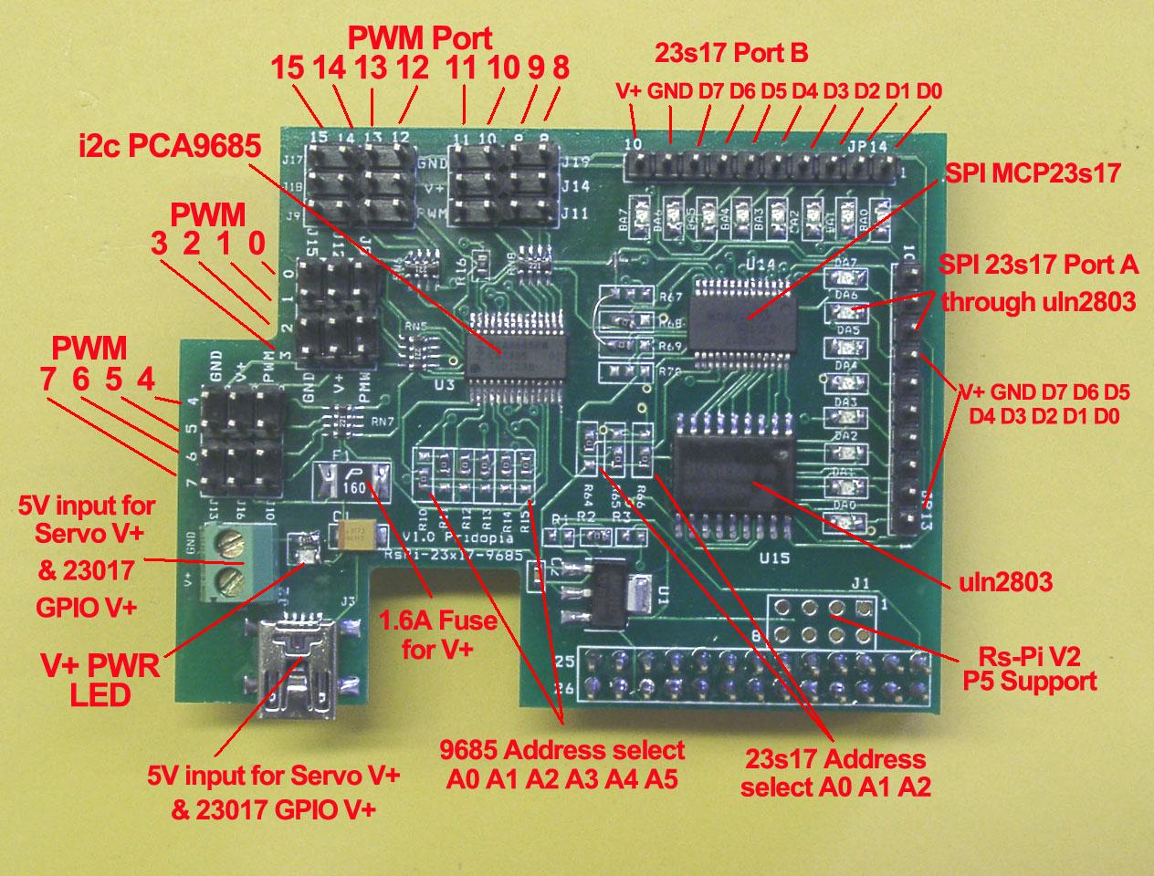
1. J3 Mini USB 5V input for PWM V+ & GPIO output pin 10 V+
J2 2P Terminal Block 5V input for PWM V+ & GPIO output pin 10 V+
2. J1 Rs-Pi V2 GPIO output
3 JP13 DA0 ~ DA7 U14 Port A . JP14 BA0 ~ BA7 U14 Port B
4. R64,R65,R66 ( for U14 Address select A0,A1,A2)
5. U14 SPI 23s17 -1 Port A,B 23s17 Datasheet
6. U15 uln2803
7. U3 PCA9685 (PWM Port 0 ~ 15) PCA9685 Data Sheet
8. R10,R11,R12,R13,R14,R15( for U3 Address select A0,A1,A2,A3,A4,A5)
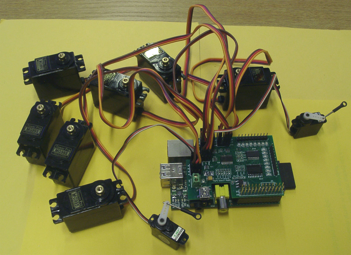
plug in Raspberry Pi with Servo motor
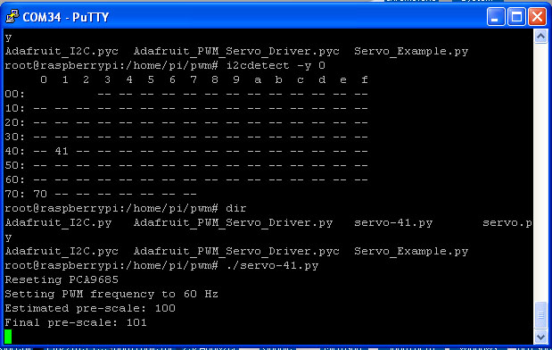
in i2cdetect you can found 1 device in system (41)
41 – 9685
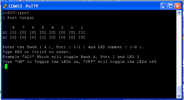
our new output test program 23s17-1port-v100.py display all 16 GPIO status
三、Scratch驅動應用範例 Detail
(1) 23s17 16 GPIO control
U1 to U4 spi 23s17 address 40,42,44,46
U1 to U2 spi 23s17 address 40,42
40 –> 1 42 –> 2 44 –> 3 46 –> 4
48 –> 5 4a –> 6 4c –> 7 4e –> 8
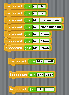
Command “sp“+ “address(1-8)” + “a” +”bit(1 to 8)” for Port A
Command “sp“+ “address(1-8)” + “b” +”bit(1 to 8)” for Port B
Command “bits“+ “address(1-8)” + “a” +”bit(8 to 1)” for Port A
Command “bits“+ “address(1-8)” + “b” +”bit(8 to 1)” for Port B
sp2b7 –> spi address 2 Port B bit 7 ON/OFF
sp3b4 –> spi address 3 Port B bit 4 ON/OFF
bits2b01010101 –> address 2 port B from bit 8 to 11
output –> 01010101
bits2a01010101 –> address 2 port A from bit 8 to 1
output–>01010101
bits2aoff –> address 2 Port A all OFF/clear
bits2aclr –> address 2 Port A all OFF/clear
(2) Servo Motor control

2 Servo in channel 0 & channel 7
Command “SE”+ “PWM (0-15)” + “a” +”angle” for Address 41
se7a10 –> channel 7 servo move 10 angle address 41
se7a-10 –> channel 7 servo move -10 angle address 41
se0a10 –> channel 0 servo move 10 angle address 41
se0a-10 –> channel 0 servo move -10 angle address 41
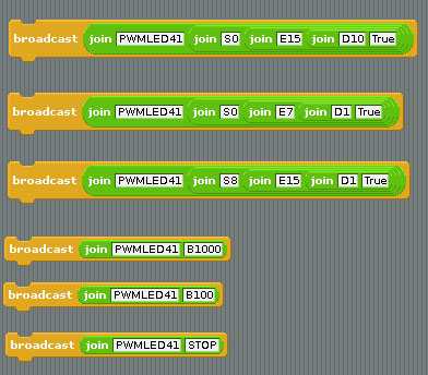
(3) PWM LED output demo


LED module (Blue, Green,Yellow,Red)
LED Scrolling Command PWMLED41S0E15D4True
PWMLED”Address” S[Start channel] E[End channel] D[Delay / Timing] [True/False]
Address 41, 42,43,44
Start channel & End channel 0 ~ 15 16 channel
D 1,2,3,4,5 (1 ~ 100) Delay Timing
LED Brightness control Command
PWMLED “Address” “B” “0 ~ 1000“
PWMLED41B1000
Stop command
“PWMLED41STOP”
四、範例程式下載
五、產品內容
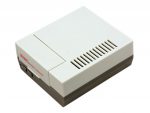
1x Rs-Pi I2C 16 channel PWM & SPI 23s17-1 16 GPIO board
1x User manual


商品評價
目前沒有評價。