描述
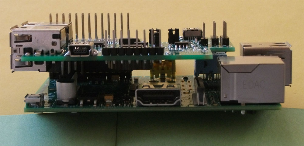

for Rs-Pi V2 i2c in bus 1
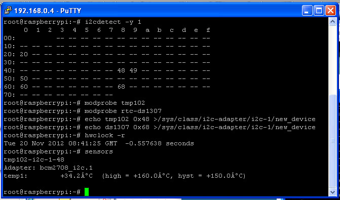
” i2cdetect -y 1 ” for i2c bus scan
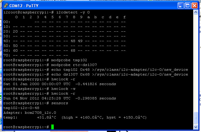
for Rs-Pi V1 i2c in bus 0
” i2cdetect -y 0 ” for i2c bus scan
i2c Bus Detect Status
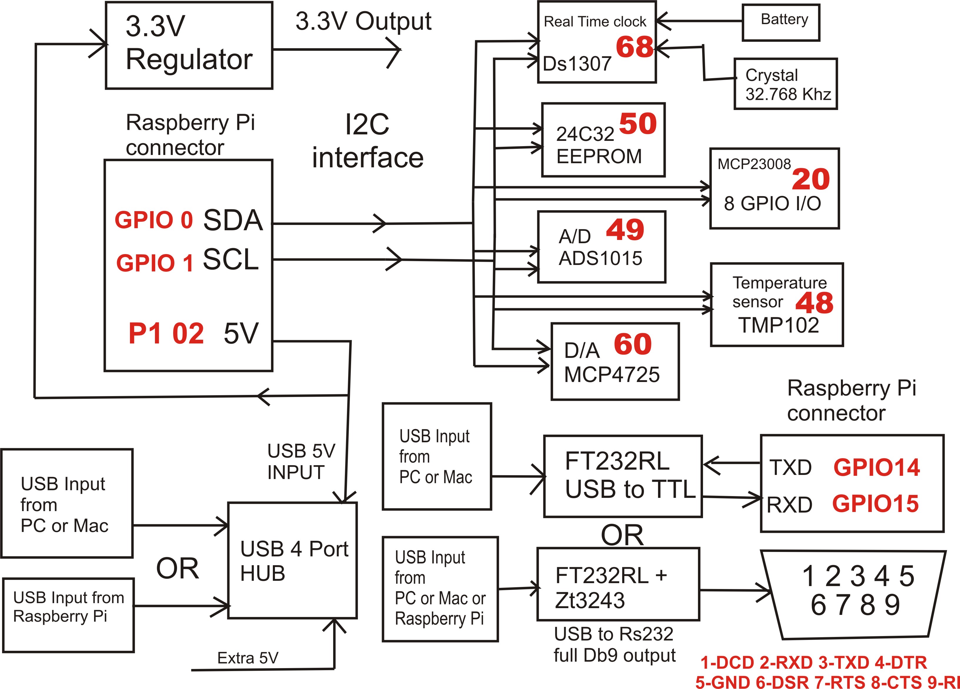
20 -> MCP23008 48 -> TMP102 68 -> RTC DS1307 50 -> 24c32
60 -> MCP4725 49-> ADS1015
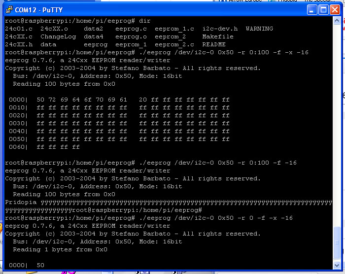
use eeprog 0.7.6 can read/write for 24c32 or 24cxx
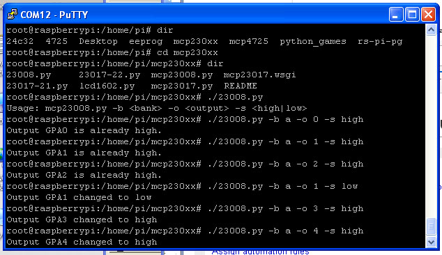
23008 8 bit GPIO use 23008.py can set each bit output high or low
MCP4725 12bit Digital-to-Analog Converter
* demo 9 bit output sinewave.py at address “60”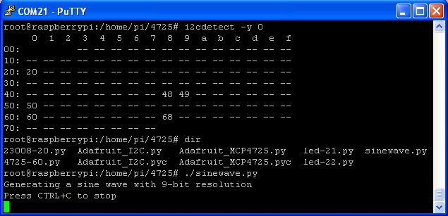
MCP4725 demo 9 bit sinewave.py at address “60”
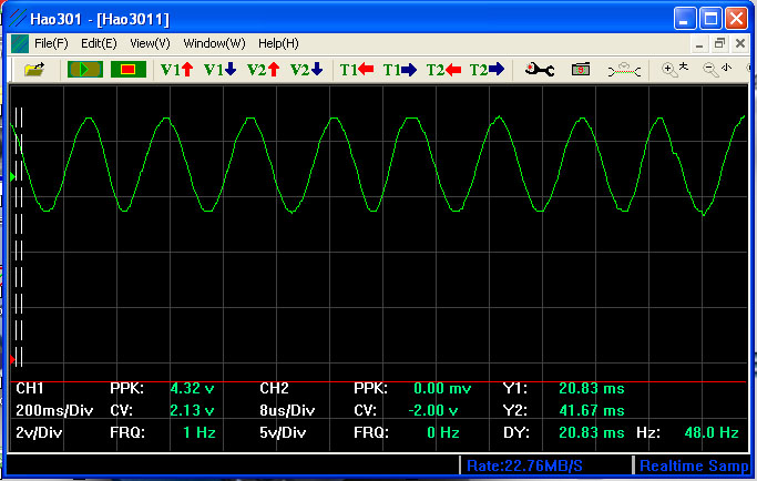
mcp4725 demo sinewave.py result
* ADS1015 12bit Analog-to-Digital Converter
demo 12 bit 4 channel input ads1015-49.py at address “49”
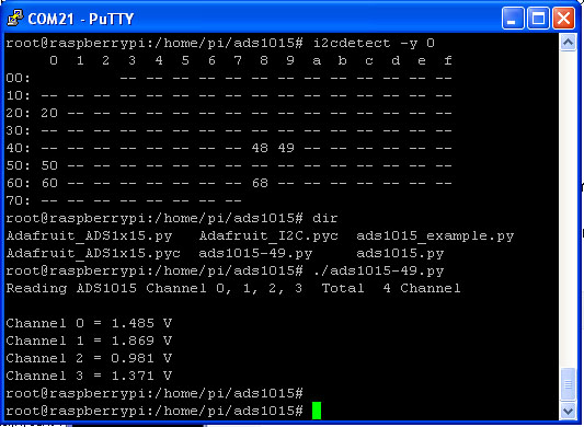
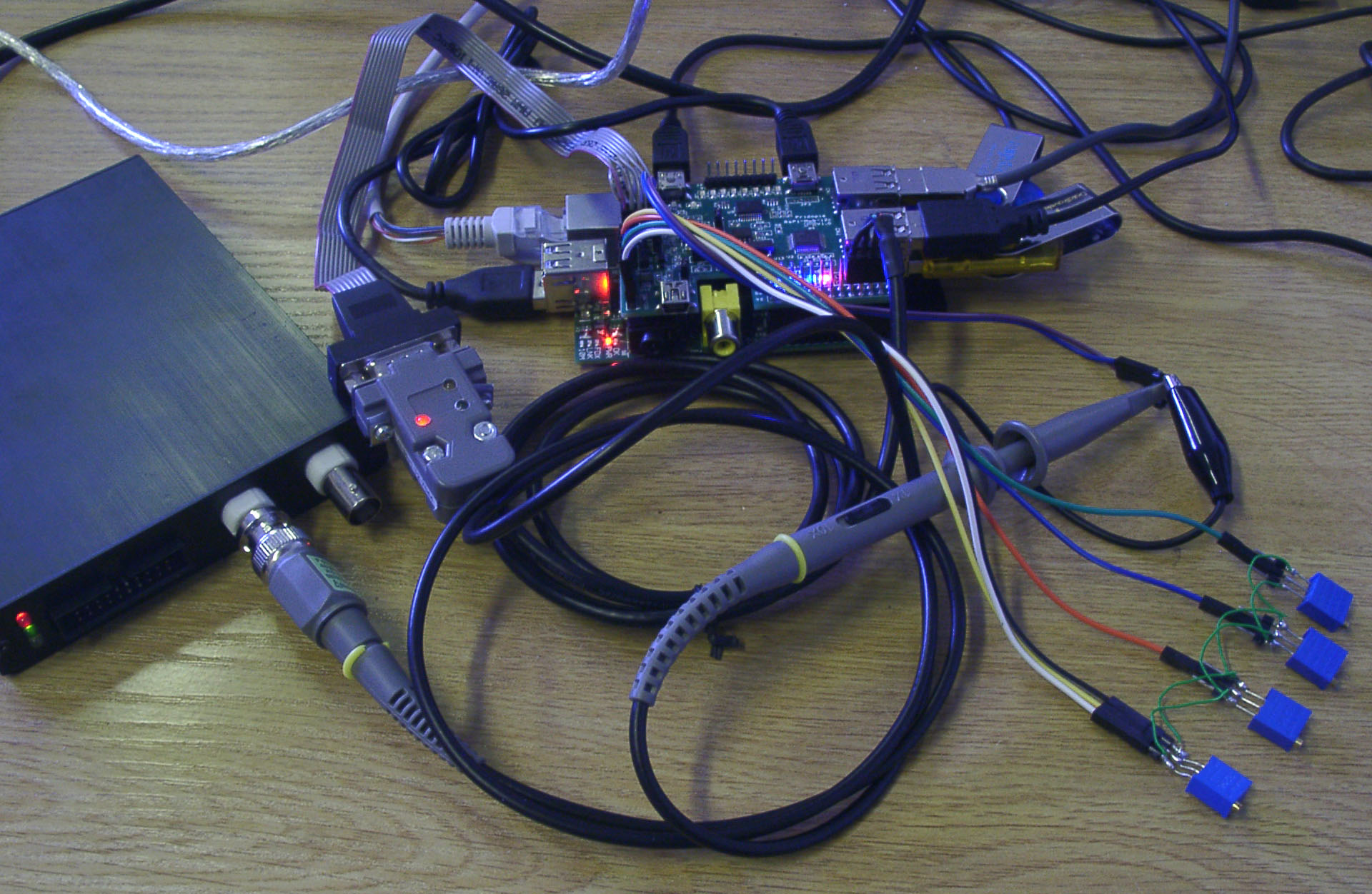
MCP4725 & ADS1015 Demo
ADS1015 use 4 trimpot 10K OHM for 4 channel Analog input
MCP4725 output to USB Digital Oscilloscope
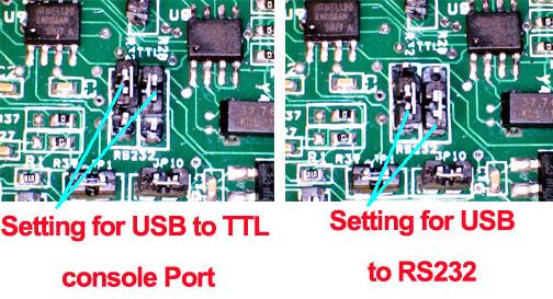
Change R28 ,R32 Jumper you can change USB-TTL
or USB-RS232 function
* USB-TTL console function, access you Rs-Pi by a normal USB A to USB Mini B cable
* USB-RS232 make your PC or Mac or Rs-Pi have full function 9 pin RS232 Port
Spec Detail
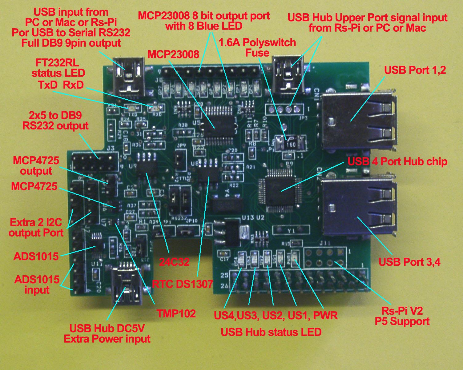
1. U5 MCP23008 J2 (GP0 ~ GP7 ) OUTPUT & GP0, GP1, GP2, GP3, GP, GP5, GP6, GP7 (8 LED OUTPUT )
R20,R21,R22 (A0,A1,A2) address select JP12 Disable Jumper Datasheet
2. U8 RTC DS1307 with CR1220 Battery Datasheet
3. U7 TMP102 Temperature Sensor Datasheet
4. U9 24C32 32Kbit EEPROM JP10 Disable Jumper Datasheet
5. U6 MCP4725 12bit Digital-to-Analog Converter , Datasheet
JP11 (AOUT, GND) JP1 Disable Jumper
6. U11 ADS1015 12bit Analog-to-Digital Converter , Datasheet
J7 INPUT (AIN0, AIN1,AIN2,AIN3,GND,3V3) JP12 Disable Jumper
7. J5 (5V, GND,SCL,SDL) J6(3v3,GND,SCL,SDL) I2C output
U2 – USB 4 Ports HUB chipset
8. J1 (JP3) USB HUB upper port signal input from Rs-Pi
9. J13 Mini USB 5V input for USB Hub, you don’t need plug 5V , the USB Hub already use 5V from Raspberry Pi (P1 pin2), if your USB device need more power, then you can plug-in 5V in this port.
10. U10 FT232RL J4 USB input from PC for USB to RS232 console port, just connect a cable (5pin mini USB-B to A USB ) then you have this console function. Datasheet
U12 ZT32433 RS232 Transceiver Driver , You can have DB9 full 9pin RS232 output from PC or Mac USB cable input or from Rs-Pi HUB Port for input Datasheet
11. J11 for RS-Pi V2 GPIO connector (got 4 more GPIO pin)
Adafruit Occidentalis v0.2 image support the
TMP102 and RTC DS1307 , ADS1015 , MCP4725
Download sample program mcp23008.py output higi or low to each bit for MCP23008 in address “20”
23008-20.py for LED chaser program Rs-Pi V1 board
23008-1-20.py for LED chaser program Rs-Pi V2 board
ads1015 sample program
Download User manual
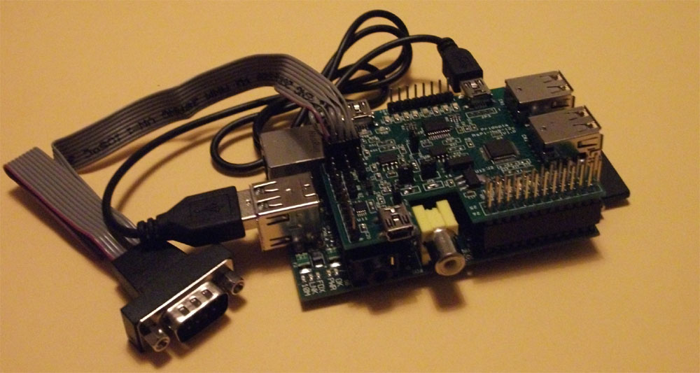
Full 9pin DB9 RS232 com port output with 30cm length cable
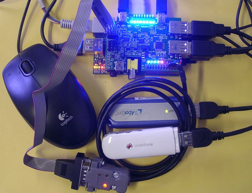
Rs-Pi USB Hub connect 4 USB devices (keyboard, Mouse, 3G dongle, Wifi Dongle)
doesn’t need extra 5V power input, The Rs-Pi RS232 console cable connect to on board
RS232 port, the USB console port connect to PC USB port.USB port.
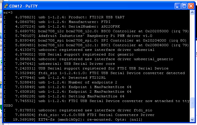
FT232RL driver loaded when System Boot
產品內容
1x Rs-Pi USB HUB & I2C w/ USB console board
1x USB to MINI USB hub input cable
1x 2.0mm pitch 2×5 to DB9 30cm cable
1x CR1220 3V Battery
1x Manual






商品評價
目前沒有評價。