描述
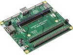
14. 樹莓派 Raspberry Pi SPI 23s17x2 32 GPIO 長針擴充板
樹莓派 Raspberry Pi – SPI 23s17 x2 – 32 GPIO Board
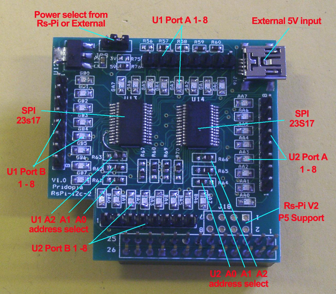
一、 Serial Peripheral Interface (SPI), Our PCB Layout design can use I2c 23017 & SPI 23S17.
二、use n23s17-cs0.py test 32 GPIO output

三、23s17 x2 32bit output demo – 32 LED

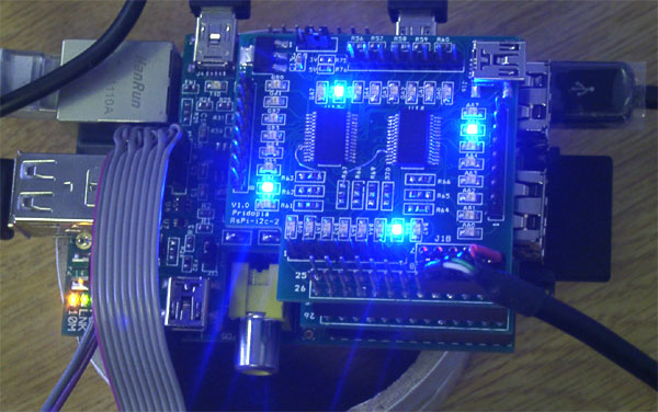
四、The U1 SPI 23s17 (address 000) can control and detect by pi-face software.

五、 new test program 23s17-2port-v3.py demo

六、our new output test program 23s17-2port-s-v103.py display all 32 GPIO status

七、產品特色
1. J16 Mini USB 5V input
2. J18 Rs-Pi V2 GPIO output
3. JP5 GA0 ~ GA7 U13 Port A JP2 AA0 ~ AA7 U13 Port B
4 JP7 BA0 ~ BA7 U14 Port A . JP6 GB0 ~ BG7 U14 Port B
5 R61,R62,R63 ( for U13 Address select A0,A1,A2 )
6. R64,R65,R66 ( for U14 Address select A0,A1,A2)
7. U13 23s17 -1 Port A,B 23s17 Datasheet
8. U14 23s17-2 Port A,B
9.JP8 jumper select use external 5V from Mini USB connect(J16) or internal 5V from Rs-Pi
10. A0, A1, A2 address
* right side GND low – 0 * left side Vcc High – 1
八、Scratch驅動應用範例 Detail
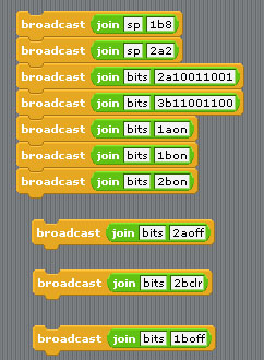
U1 to U2 spi 23s17 address 40,42
40 –> 1 42 –> 2 44 –> 3 46 –> 4
48 –> 5 4a –> 6 4c –> 7 4e –> 8
Command “sp”+ “address(1-8)” + “a” +”bit(1 to 8)” for Port A
Command “sp”+ “address(1-8)” + “b” +”bit(1 to 8)” for Port B
Command “bits”+ “address(1-8)” + “a” +”bit(8 to 1)” for Port A
Command “bits”+ “address(1-8)” + “b” +”bit(8 to 1)” for Port B
sp2b7 –> spi address 2 Port B bit 7 ON/OFF
sp3b4 –> spi address 3 Port B bit 4 ON/OFF
bits2b01010101 –> address 2 port B from bit 8 to 11
output –> 01010101
bits2a01010101 –> address 2 port A from bit 8 to 1
output –>01010101
bits2aoff –> address 2 Port A all OFF/clear
bits2aclr –> address 2 Port A all OFF/clear
九、範例程式下載
十、產品內容
1x Rs-Pi SPI 23s17-2 32 GPIO board
1x User manual



商品評價
目前沒有評價。